| Interface standard(s) |
CoaXPress 1.0, 1.1, 1.1.1 and 2.0 |
| Connectors |
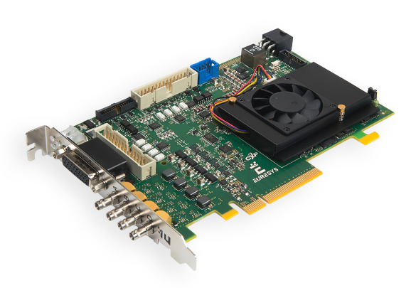
Four micro-BNC 75 Ohms (also known as HD-BNC™) CXP-12 |
| Status LEDs |
One CoaXPress Host connection status LED per connection |
| Number of cameras |
Area-scan cameras:
One 1- or 2- or 4-connection camera
Four 1-connection cameras
Line-scan cameras:
One 1- or 2- or 4-connection camera |
| Maximum aggregated camera data transfer rate |
50 Gbit/s (5,000 MB/s) |
| Supported CXP down-connection speeds |
1.25 GT/s (CXP-1), 2.5 GT/s (CXP-2), 3.125 GT/s (CXP-3), 5 GT/s (CXP-5), 6.25 GT/s (CXP-6), 10.0 GT/s (CXP-10), and 12.5 GT/s (CXP-12) |
| Supported CXP up-connection speeds |
- Low-speed 20.83… Mbps (CXP-1 to CXP-6)
- Low-speed 41.66… Mbps (CXP-10, CXP-12)
|
| Number of CXP data streams (per camera) |
1 data stream per camera |
| Maximum CXP stream packet size |
16,384 bytes |
| PoCXP (Power over CoaXPress) |
- PoCXP Safe Power:
- 17 W of 24V DC regulated power per CoaXPress connector
- PoCXP Device detection and automatic power-on
- Overload and short-circuit protections
- On-board 12V to 24V DC/DC converter
- A +12V power source must be connected to the AUXILIARY POWER INPUT connector using a 6-pin PEG cable
|
| Camera types |
- Area-scan cameras:
- Grayscale and color (YCbCr, YUV, RGB and Bayer CFA)
- Single-tap (1X-1Y) progressive-scan
- Line-scan cameras and contact imaging sensors:
|
| Camera pixel formats supported |
Raw, Monochrome, Bayer, RGB, and RGBA (PFNC names):
- Raw
- Mono8, Mono10, Mono12, Mono14, Mono16
- BayerXX8, BayerXX10, BayerXX12, BayerXX14, BayerXX16 where XX = GR, RG, GB, or BG
- RGB8, RGB10, RGB12, RGB14, RGB16
- RGBA8, RGBA10, RGBA12, RGBA14, RGBA16
- YCbCr601_422_8, YCbCr601_422_10
- YCbCr709_422_8, YCbCr709_422_10
- YUV422_8, YUV422_10
|
| On-board processing |
| On-board memory |
4 GB |
| Image data stream processing |
- Unpacking of 10-/12-/14-bit to 16-bit with selectable justification to LSb or MSb
- Optional swap of R and B components
- Little endian conversion
|
| Input LUT (Lookup Table) |
Only available for monochrome cameras:
- 8 to 8 bits
- 10 to 8, 10 or 16 bits
- 12 to 8, 12 or 16 bits
|
| Bayer CFA to RGB decoder |
- ‘1-camera’ firmware variant:
- 3×3 linear interpolation method
- 3×3 median-based interpolation method
|
| CustomLogic firmware variants |
- 1-camera, customlogic firmware variant
- one 1- or 2- or 4-connection area-scan camera
- 91% DSP, 82% FF, 74% LUT and 56% BRAM resources of the Xilinx Kintex Ultrascale XCKU035 FPGA available for user programming
- 2GB capacity, 12GB/s bandwidth, shared on-board DRAM memory
|
| Data stream statistics |
- Measurement of:
- Frame rate (Area-scan only)
- Line rate
- Data rate
- Configurable averaging interval
|
| Event signaling and counting |
- The application software can be notified of the occurrence of various events:
- Standard event: the EVENT_NEW_BUFFER event notifies the application of newly filled buffers
- A large set of custom events
- Custom events sources:
- I/O Toolbox events
- Camera and Illumination control events
- CoaXPress data stream events
- CoaXPress host interface events
- Each custom event is associated with a 32-bit counter that counts the number of occurrences
- The last three 32-bit context data words of the event context data can be configured with event-specific context data:
- Event-specific data
- State of all System I/O lines sampled at the event occurrence time
- Value of any event counter
|
| C2C-Link |
| Description |
- Accurate synchronization of the trigger and the start-of-exposure of multiple grabber-controlled area-scan cameras.
- Accurate synchronization of the start-of-cycle, start-of-scan and end-of-scan of multiple grabber-controlled line-scan cameras.
|
| Specification |
- C2C-Link synchronizes cameras connected to:
- the same card
- to different cards in the same PC (requires an accessory cable such as the “3303 C2C-Link Ribbon Cable” or a custom-made C2C-Link cable)
- to different cards in different PCs (requires one “1636 InterPC C2C-Link Adapter” for each PC and one RJ 45 CAT 5 STP straight LAN cable for each adapter but the last one)
- Maximum distance:
- 60 cm inside a PC
- 1200 m cumulated adapter to adapter cable length
- Maximum trigger rate:
- 2.5 MHz for configurations using a single PC, or up to 10 PCs and 100 m total C2C-Link cable length
- 200 kHz for configurations up to 32 PCs and 1200m total C2C-Link cable length
- Trigger propagation delay from master to slave devices:
- Less than 10 ns for cameras on the same card or on different cards in the same PC
- Less than 265 ns for cameras on different cards in different PCs (3 PCs and 40m total C2C-Link cable length)
|


