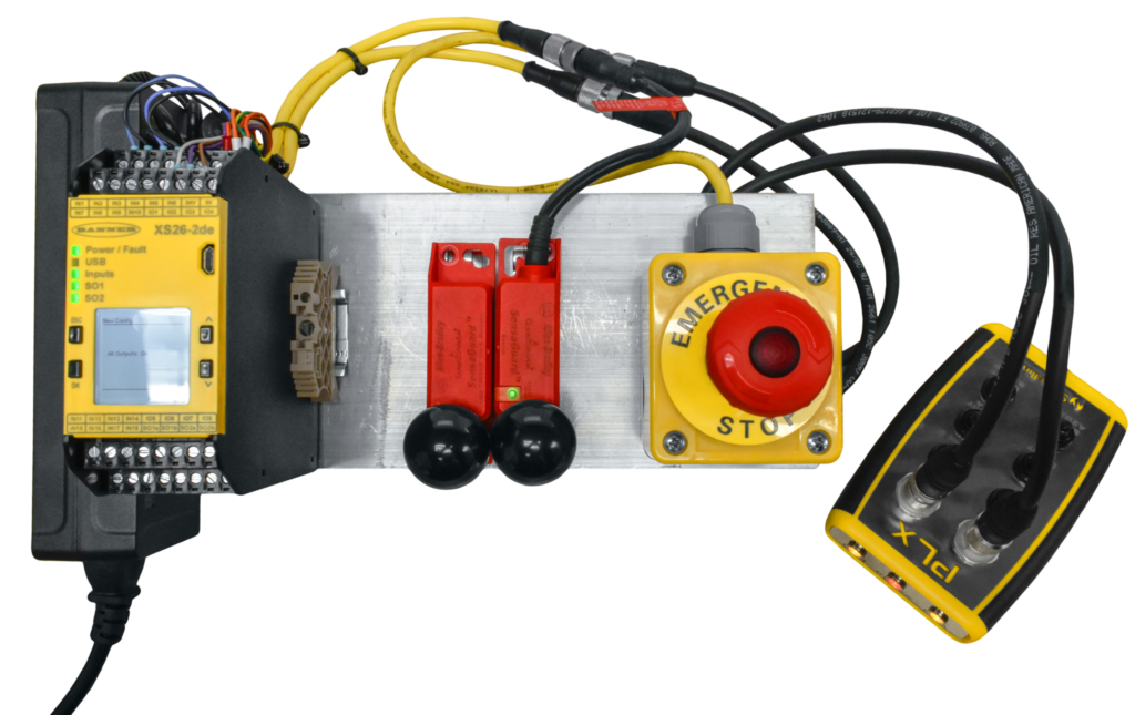
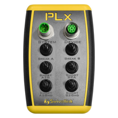
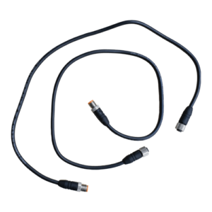
The design of the PLx allows it to be quickly inserted into systems though its quick disconnect connector interface that will be available in multiple formats. The PLx base model uses an 8-Pin M12 quick-disconnect connector. Using extension or adapter cables as necessary, insert the PLx in series with the device to be tested. The “device” port is connected to the safety device, and the “System” Port is connected to the safety controller.
The PLx can then be used to validate the safety system. This is accomplished by intercepting and manipulating the safety device’s signals and power connections. The user can induce faults into the safety system and control the safety device’s functions through manipulation of an array of switches on the PLx. Status indicators of the safety device’s signals and power are provided on the PLx unit for observing the status and results of the safety device while in operation and during fault induction testing.
Faults Able to be Induced:
- Single Channel Break (x2 Ch A & Ch B)
- Cross Short Between Channels (x2 Short A-2-B & B-2-A)
- Short Channel to Ground (x2 A-2-GND & B-2-GND) Faults
The PLx is a universal device designed to insert in series with equipment safety devices and induce faults into that safety system to validate the functionality and diagnostic coverage of the safety system.
Properly used, the PLx will validate that the proper safety design Performance Level has been achieved by: design, wiring, and programming. This type of testing is required by the ISO 13849-2 safety standard.
Who is the PLx for?
The primary users of the PLx are: Environmental, Health, and Safety Professionals; Maintenance and Plant Safety Personnel; Industrial, Mechanical, Electrical, Control Engineers, and Technicians; Original equipment Manufacturers, Machinery Builders, and Systems Integrators; Equipment and Component Manufacturers and Suppliers; Educators and Students; Safety Specialists; and any person wishing to validate their machinery safety functions.
How do I know my device is compatible for use with the PLx?
The PLx base model is designed with the following pin configuration:
- Pin2 +24VDC
- Pin7 0VDC
- Pin5 ChA / OSSD1
- Pin6 ChB / OSSD2
Device manufacture may have different pinouts. Adapter cables can be purchased or made to connect virtually any standard safety device to the PLx.
How does the PLx differ from current practices?
The PLx removes the person from interfacing with the wiring and enclosure. It can be safely introduced into the system at the device or the device connection’s quick disconnect. The PLx can remain in the circuit during the entire diagnostic and fault induction testing and be removed when all testing is completed. This method improves both the safety of performing the functional testing as well as increasing the efficiency of the diagnostic and testing functions.
Designs are currently underway for expansion of the capability the PLx. Including additional fault induction, connection and manipulation of solenoid operating devices, and the additional features to accommodate variations of safety controller functions.


