| PIN |
SIGNAL |
FUNCTION |
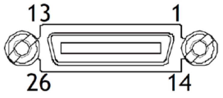
| 1,26 |
Power |
+11VDC to +13VDC Input |
| 13,14 |
GND |
Power Return |
| 2,15 |
–/+ TxOUT 0 |
CL Video Channel 1 |
| 3,16 |
–/+ TxOUT 1 |
| 4,17 |
–/+ TxOUT 2 |
| 5,18 |
–/+ TxClk |
| 6,19 |
–/+ TxOUT 3 |
| 7,20 |
+/– RXD |
Serial in |
| 8,21 |
–/+ TXD |
Serial out |
| 9,22 |
CC1–/CC1+ |
Ext. trigger |
| 10,23 |
CC2+/CC2– |
Reserved |
| 11,24 |
CC3–/CC3+ |
Not used |
| 12,25 |
CC4+/CC4– |
Not used |
For Medium and Full implementations a second Mini-CL Interface is provided. Video Channel 2 is on pin pairs (2,15), (3,16), (4,17), (5,18), and (6,19). Video Channel 3 is on pin pairs (8,21), (9,22), (10,23), (11,24), and (12,25). Consult manual for Specific bit depths and pin assignments. |
| PIN |
SIGNAL |
FUNCTION |
| 1 |
DC Power IN |
+12 to =24 VDC ± 10% |
| 2 |
Input |
TTL in, Line 4 |
| 3 |
Output |
TTL out, Line 1 |
| 4 |
GND |
Ground |
COMPATIBLE CONNECTORS:
- Camera Side: 09-3111-81-04 (Binder)
- Cable Side: 79-3108-52-04 (Binder) AWG 26 or 79-3108-32-04 (Binder) AWG 24
|


