SPECIFICATIONS
| MODEL |
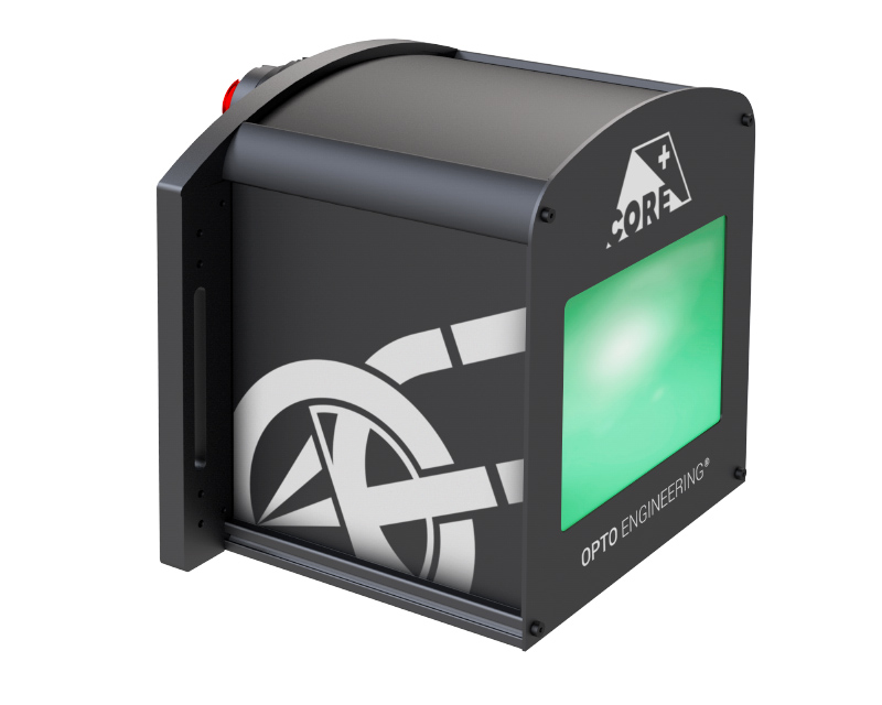
LT CL CP 144 G |
| Color (Wavelength) |
GREEN (520 nm) |
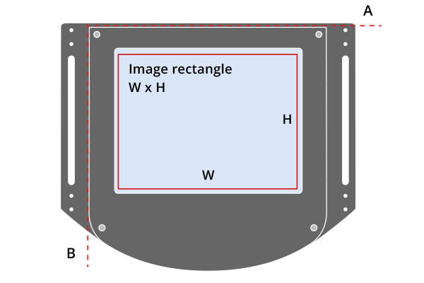
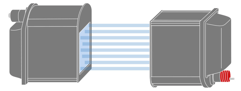
| Minimum Beam Shape Dimensions (see diagram below) |
165 x 120 |
| Working Distance Range |
170 – 350 mm |
ELECTRICAL
| DC Voltage MINIMUM |
12 Volts |
| DC Voltage MAXIMUM |
24 Volts |
| Power Consumption |
< 2.5 Watts |
| Maximum LED Forward Current |
350 ma |
| LED Forward Voltage (typical) |
3.30 V |
| LED Forward Voltage (maximum) |
4.00 V |
| LED Maximum Pulse Current |
2000 ma |
MECHANICAL
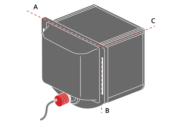
| DIMENSION A (see diagram below) |
332.0 mm |
| DIMENSION B |
302.5 mm |
| DIMENSION C |
310.5 mm |
| MASS |
6,000 g |
SAFETY AND CERTIFICATIONS
| RISK GROUP per CEI EN 62471:2010 |
RISK GROUP 1 |
MECHANICAL & PINOUT
MECHANICAL DRAWING
DP27596-A
POWER CABLE WIRING GUIDE
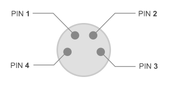 DEVICE SIDE CONNECTOR – Male Pins, Front View DEVICE SIDE CONNECTOR – Male Pins, Front View |
| PIN |
FUNCTION |
| 1 |
EARTH GROUND |
| 2 |
POWER SUPPLY GROUND |
| 3 |
LED ANODE (carefully use for trigger mode only) |
| 4 |
+ POWER SUPPLY (+ 12V ~ +24V) |
|
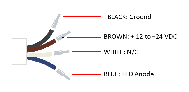
FLYING LEAD SIDE
|
| WIRE COLOR |
FUNCTION |
| BLACK |
POWER GROUND |
| BROWN |
POWER INPUT: +12 ~ +24 VDC |
| WHITE |
NO CONNECTION |
| BLUE |
LED ANODE (use for triggering or with external current controller) |
|
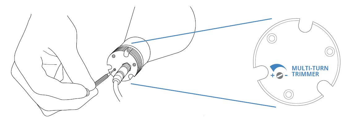
ONBOARD INTENSITY CONTROL
