GPIO
GENERAL PURPOSE INPUT AND OUTPUT (GPIO)
| Number of lines |
32 I/O lines:
- 4 contact inputs (Factory I/O: IN)
- 12 relay outputs (Factory I/O: OUT)
- 4 TTL inputs/outputs (System: IO)
- 4 differential inputs (System: TR)
- 4 opto-isolated outputs (System: ST)
- 4 full-duplex serial com ports (Camera COM: RX/TX)
|
| Connectors |
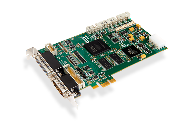
- EXTERNAL SYSTEM: 26-pin high-density male sub-D connector on the bracket
- INTERNAL SYSTEM: 26-pin dual-row 0.1″ shrouded header on the PCB
- FACTORY I/O: 34-pin dual-row 0.1″ shrouded header on the PCB
- CAMERA COM: 16-pin dual-row 0.1″ shrouded header on the PCB
- Molex 4-pin connector on the PCB for powering cameras
|
| Usage |
- Camera and image acquisition trigger
- Light strobe trigger
- General purpose IO
|
| Electrical specifications |
- TR: Inputs compatible with TTL, LVTTL, differential LVDS, differential RS-422, differential RS-485 signals, protected against electrostatic discharge, with choke for the rejection of common-mode noise
- ST: Opto-isolated outputs, compatible with signals up to 60V, with 3 µs fall time, isolated up to 500V
- IO: Inputs or outputs compatible with TTL signals, protected against electrostatic discharge, with high-frequency noise filter
- IN: Polarity-free inputs, compatible with TTL, 12V and 24V signals, opto-couplers, relays and switches
- OUT: Opto-isolated potential-free and polarity-free solid-state outputs, compatible with signals up to 30V, with 4 µs fall time, isolated up to 500V
- COM: RS232 asynchronous serial communication lines to control the cameras (exposed to the OS as standard COM ports)
|


